This document is valid for both pulsed and continuous sources of UV radiation where the exposure duration is not less than 0.1 ms. It does not apply to UV lasers. Exposure to lasers are covered by laser standard AS/NZS IEC 60825.1 Safety of laser products.
To fulfil the requirements of section 2.1 of RPS 12 supplementary information and management plans for controlling exposure to UVR can be found on the ARPANSA website:
Exposure limit: the exposure which it is believed that nearly all workers can be repeatedly exposed to without adverse effect (exposure limits for UV are given in Schedule 1 of RPS 12).
Note: The exposure limits apply to artificial sources of UVR. Due to highly variable ambient solar UVR levels the application of exposure limits is not practical and limiting solar UVR exposure to as low as possible is the most effective approach.
Permissible exposure time, tPET: the time it takes to reach the exposure limit (calculated according to Schedule 1 of RPS 12).
3. Controlled apparatus
In section 4 Group 1 table of the Regulations defines an optical source, other than a laser product, emitting ultraviolet radiation, infrared or visible light as controlled apparatus.
4. Criteria to be satisfied
Section 9 of the Regulations consists of two separate criteria, both of which must be fulfilled for the apparatus to be classed as controlled apparatus.
The first criterion, paragraph 9(1)(b) concerns source emission. It is fulfilled if the apparatus produces non-ionising radiation that could lead to a person being exposed to radiation levels exceeding the non-ionizing radiation exposure limits. For UVR the relevant standard referred to in section 4 is Radiation Protection Standard for Occupational Exposure to Ultraviolet Radiation (2006), ARPANSA Radiation Protection Series No. 12 (RPS 12).
The second criterion, paragraph 9(1)(c) is based on the accessibility of the source. Factors determining whether radiation above the exposure limits is accessible to persons have to be evaluated. The condition is fulfilled if excess levels of radiation are readily accessible to persons in any of the following situations:
in the course of intended operations or procedures of the apparatus; or
as a result of a reasonably foreseeable abnormal event involving the apparatus; or
as a result of a reasonably foreseeable single element failure of the apparatus; or
without the use of tools or other specialised equipment required to remove protective barriers or access panels.
If the apparatus is not one of the exempt dealings in section 44(7) of the Regulations the procedure in the next section describes how to go through these two criteria to determine whether a UVR source is classed as controlled apparatus or not.
5. Procedure
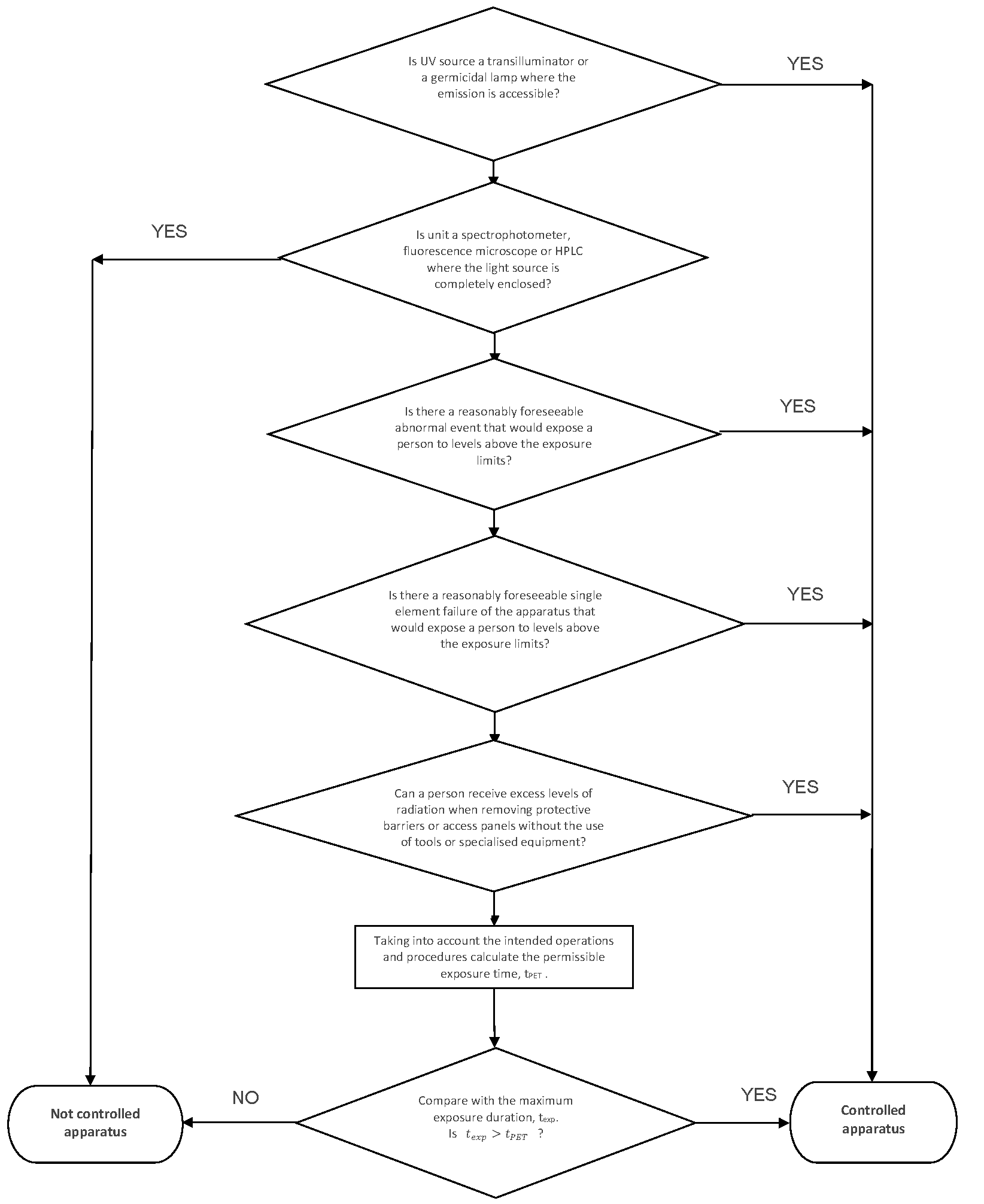
This procedure (as show by the flow chart on page 4) will assist you to determine whether your apparatus is controlled or not.
If the apparatus is a transilluminator or germicidal lamp where the emission is accessible, it is classed as controlled apparatus.
If the apparatus is a fluorescence microscope, a spectrophotometer or a high-performance liquid chromatography (HPLC) where the light source is completely enclosed, it is not controlled apparatus.
If there is a reasonably foreseeable abnormal event involving the apparatus that would lead to a person being exposed to levels above the exposure limits, the apparatus is classed as controlled apparatus. Examples of this are: forgetting or using the wrong PPE, possible exposure during normal maintenance, not using prescribed shielding to cover a sample, easy overriding of an interlock etc.
If there is a reasonably foreseeable single element failure of the apparatus that would lead to a person being exposed to levels above the exposure limits, the apparatus is classed as controlled apparatus. An example of this is a malfunctioning interlock. A failsafe interlock would not lead to a person being exposed as no UVR is emitted if the interlock fails.
If a person can receive excess levels of radiation when removing protective barriers or access panels that do not require the use of tools or other specialised equipment, then the apparatus is classed as controlled apparatus.
Determine if the source emits UV radiation that could lead to a person being exposed to radiation levels in excess of the exposure limits in the course of intended operations or procedures. Calculate the permissible exposure time, tPET, according to the method described in Schedule 1 of RPS 12.
Notes:
The distance to the source when the unit is in operation should be taken into account. Using the inverse square law the radiation level is calculated at the position where the closest person is situated. If the unit is handheld and no distances are specified: assume that the skin and eyes are 20 cm and 50 cm, respectively, from the source.
Embedded devices can be designed in such a way that it can be considered safe for their intended use and during normal operation as the emission hazard only becomes accessible during service or maintenance. i.e. protective housing, interlocks and other organisational safety measures. The servicing of embedded UV sources can increase the risk of injury as the servicing may include various adjustments. To carry out servicing in a safe manner it may be necessary to implement temporary procedures and safeguards appropriate to the increased level of risk. Manufacturers may provide advice on safe procedures during servicing and maintenance.
Compare with the maximum exposure duration, texp.
If texp>tPET the apparatus is classed as controlled apparatus.
If the apparatus is not classed as controlled apparatus.
Flowchart for determining whether a UV source is a controlled apparatus
Appendix 1
Extracts from Schedule 1 Radiation Protection Standard for Occupational Exposure to Ultraviolet Radiation (2006)
Radiation Protection Series No. 12
Exposure Limits (EL) for UVR from Artificial Sources 1
S1.1
The EL for occupational exposure to UVR incident upon the skin or eye where irradiance values are known and the exposure duration is controlled are as below. Note that S1.2 and S1.3 must both be satisfied independently.
S1.2
For the UV-A spectral region 315 to 400 nm, the total radiant exposure on the unprotected eye must not exceed 10 kJ.m–2 within an 8 hour period and the total 8 hour radiant exposure incident on the unprotected skin must not exceed the values given in Table 1. Values for the relative spectral effectiveness are given up to 400 nm to expand the action spectrum into the UV-A for determining the EL for skin exposure.
S1.3
In addition, the ultraviolet radiant exposure in the actinic UV spectral region (UV-B and UV-C from 180 to 315 nm) incident upon the unprotected skin and unprotected eye(s) within an 8 hour period must not exceed the values given in Table 1.
S1.4
For broadband sources emitting a range of wavelengths in the ultraviolet region (ie most UVR sources), determination of the effective irradiance of such a broadband source is done by weighting all wavelengths present in the emission with their corresponding spectral effectiveness by using the following weighting formula:
Eeff = ∑Eλ. Sλ. ∆λ
where
Eeff = Effective irradiance in W.m–2 (J.s–1.m–2) normalised to a monochromatic source at 270 nm
Eλ = Spectral irradiance in W.m–2.nm
Sλ = Relative spectral effectiveness (unitless)
∆λ = Bandwidth in nanometres of the calculated or measurement intervals
S1.5
Permissible exposure time in seconds for exposure to actinic UVR incident upon the unprotected skin or eye may be computed by dividing 30 J.m–2 by Eeff in W.m–2. The maximum exposure duration may also be determined using Table 2 of this Schedule which provides representative exposure durations corresponding to effective irradiances in W.m–2 (and μW.cm-2).
1 These exposure limits are intended to be used as guidelines only for Solar UVR exposure.
Table 1: Ultraviolet radiation exposure limits and Relative Spectral Effectiveness
Wavelengtha
(nm)
Exposure limit
(J.m-2)
Exposure limit
(mJ.cm-2)
Relative Spectral Effectiveness Sλ
180
2 500
250
0.012
190
1 600
160
0.019
200
1 000
100
0.030
205
590
59
0.051
210
400
40
0.075
215
320
32
0.095
220
250
25
0.120
225
200
20
0.150
230
160
16
0.190
235
130
13
0.240
240
100
10
0.300
245
83
8.3
0.360
250
70
7.0
0.430
254b
60
6.0
0.500
255
58
5.8
0.520
260
46
4.6
0.650
265
37
3.7
0.810
270
30
3.0
1.000
275
31
3.1
0.960
280b
34
3.4
0.880
285
39
3.9
0.770
290
47
4.7
0.640
295
56
5.6
0.540
297b
65
6.5
0.460
300
100
10
0.300
303b
250
25
0.120
305
500
50
0.060
308
1 200
120
0.026
310
2 000
200
0.015
313b
5 000
500
0.006
315
1.0 × 10⁴
1.0 × 10³
0.003
316
1.3 × 10⁴
1.3 × 10³
0.0024
317
1.5 × 10⁴
1.5 × 10³
0.0020
318
1.9 × 10⁴
1.9 × 10³
0.0016
319
2.5 × 10⁴
2.5 × 10³
0.0012
320
2.9 × 10⁴
2.9 × 10³
0.0010
322
4.5 × 10⁴
4.5 × 10³
0.00067
323
5.6 × 10⁴
5.6 × 10³
0.00054
325
6.0 × 10⁴
6.0 × 10³
0.00050
328
6.8 × 10⁴
6.8 × 10³
0.00044
330
7.3 × 10⁴
7.3 × 10³
0.00041
333
8.1 × 10⁴
8.1 × 10³
0.00037
335
8.8 × 10⁴
8.8 × 10³
0.00034
340
1.1 × 10⁵
1.1 × 10⁴
0.00028
345
1.3 × 10⁵
1.3 × 10⁴
0.00024
350
1.5 × 10⁵
1.5 × 10⁴
0.00020
355
1.9 × 10⁵
1.9 × 10⁴
0.00016
360
2.3 × 10⁵
2.3 × 10⁴
0.00013
365b
2.7 × 10⁵
2.7 × 10⁴
0.00011
370
3.2 × 10⁵
3.2 × 10⁴
0.000093
375
3.9 × 10⁵
3.9 × 10⁴
0.000077
380
4.7 × 10⁵
4.7 × 10⁴
0.000064
385
5.7 × 10⁵
5.7 × 10⁴
0.000053
390
6.8 × 10⁵
6.8 × 10⁴
0.000044
395
8.3 × 10⁵
8.3 × 10⁴
0.000036
400
1.0 × 10⁶
1.0 × 10⁵
0.000030
a Wavelengths chosen are representative; other values should be interpolated at intermediate wavelengths
b Emission lines of a mercury discharge spectrum
Table 2: Limiting UV exposure durations based on EL
This document is provided to assist controlled persons to determine whether a Class 1M and Class 2M source is classed as a controlled apparatus under the Australian Radiation Protection and Nuclear Safety Act 1998 (the Act). In particular, it clarifies the conditions used in section 9 of the Australian Radiation Protection and Nuclear Safety Regulations 2018 (the Regulations).
Reference documents
AS/NZS IEC 60825.1 Safety of laser products Part 1: Equipment classification and requirements
AS/NZS IEC 60825.2 Safety of laser products Part 2: Safety of optical fibre communication systems (OFCS)
AS/NZS IEC 60825.14 Safety of laser products Part 14: A user’s guide
2. Background
There are currently eight classifications for lasers based on the likelihood of injury. The classification of a laser is used to develop safety control measures. The Accessible Emission Limit (AEL) is the maximum accessible emission permitted within a particular class of laser.
In section 44(7) of the Regulations the exempt dealings define a laser as an exempt laser product with an accessible emission that does not exceed the accessible emission limits of a Class 3R laser product, as set out in AS/NZS IEC 60825.1 and an optical fibre communication system that does not exceed the hazard level 3R, as set out in AS/NZS IEC 60825.2.
Therefore, a laser with an AEL greater than the accessible emission limit of a Class 3R laser product is deemed a controlled apparatus and an optical fibre communication system where it exceeds a Hazard Level 3R as a controlled apparatus.
Because the emission level of Class 1M and Class 2M laser products may exceed the AEL for Class 3R, Class 1M and Class 2M lasers are potentially classified as controlled apparatus.
3. Class 1M lasers
A Class 1M laser is any laser product in the wavelength range from 302.5 nm to 4000 nm.
Since Class 1M is assigned to lasers where the exposure would not normally exceed the AEL of Class 1, most Class 1M lasers would not be considered to be a controlled apparatus.
The two notable exceptions to this would be where it is reasonably foreseeable that the beam may be viewed with magnifying optics like a telescope, binoculars or a microscope. Consequently the AEL may be greater than the AEL of a Class 3R laser:
where the beam is collimated with a large diameter and optics are used to focus the beam, or
where the beam is highly divergent and optics are used near the laser aperture to collimate the beam.
Example: Laser diodes, fibre communication systems.
4. Class 2M lasers
Class 2M laser is any laser product in the wavelength range from 400 nm to 700 nm.
Class 2M applies only to visible lasers and assumes that a degree of protection is afforded by the aversion response (blinking and turning away). In most cases, due to the aversion response, it is not considered reasonably foreseeable that a person would deliberately view the beam for more than 0.25s. The same conditions given for Class 1M lasers apply to Class 2M lasers: unless the beam is viewed with magnifying optics it is not considered to be a controlled apparatus.
Warning for potential hazard to the skin or eye
If the accessible emission from a Class 1M or Class 2M laser is greater than the AEL of a Class 3R as determined with a 3.5 mm diameter aperture placed at the closest point of human access, an additional warning regarding potential skin hazard and/or anterior parts of the eye hazard must be given. The following additional warning must be given on the device:
Hazard level 1M and 2M optical fibre communications systems (OFCS)
Hazard level refers to the potential hazard from laser emissions at any location in an end-to-end fibre optic communication system that may be accessible during use or maintenance or in the event of a failure or fibre disconnection as described in AS/NZS IEC 60825.2. The assessment of the hazard level uses the class AEL described in AS/NZS IEC 60825.1.
Hazard level 1M and Hazard level 2M OFCS may be considered to be controlled if their emission level exceeds the AEL for Class 3R and in the course of intended operations or under a reasonably foreseeable abnormal event, may lead to persons being exposed to emission in excess of the MPE mentioned in AS/NZS IEC 60825.1. Each accessible location in an extended enclosed optical transmission system will be designated by a hazard level as those for classifications in AS/NZS IEC 60825.1 and based on radiation that could become accessible and exceeds the AEL for Class 3R under reasonably foreseeable circumstances such as a fibre cable break or disconnected fibre connector. Labelling and marking requirements can be found in AS/NZS IEC 60825.2.
5. Summary
Class 1M and Class 2M lasers may be considered to be controlled if their emission level exceeds the AEL for Class 3R and in the course of intended operations or under a reasonably foreseeable abnormal event, may lead to persons being exposed to emission in excess of the MPE mentioned in AS/NZS IEC 60825.1.
For the purposes of determining the hazard level of 1M and 2M optical fibre communications systems, the same rules apply as for Class 1M and 2M lasers.
This document is provided to assist controlled persons to determine whether a radiofrequency (RF) source is classed as a controlled apparatus under the Australian Radiation Protection and Nuclear Safety Act 1998 (the Act). In particular, it clarifies conditions and defines terms used in Section 9 of the Australian Radiation Protection and Nuclear Safety Regulations 2018 (the Regulations).
2. Controlled apparatus
The Group 1 table in section 4 of the Regulations defines some of the types of RF emitting devices which are classed as controlled apparatus.
The following are examples of RF devices:
a magnetic field non-destructive testing device
an induction heater or induction furnace
an industrial radiofrequency heater or welder
a radiofrequency plasma tube
microwave or radiofrequency diathermy equipment
an industrial microwave or radiofrequency processing system
More explanatory examples of the above listed RF emitting devices can be found in Appendix 1.
Note: In section 44 (7) of the Regulations exempt dealings for the following RF emitting devices:
radar equipment used for detection and ranging
radiofrequency equipment used for communications
Klystron
3. Criteria to be satisfied
Section 9 of the Regulations consists of two separate criteria, both of which must be fulfilled for the apparatus to be classed as controlled apparatus.
The first criterion paragraph 9(1)(b) concerns source emission. It is fulfilled if the apparatus produces non-ionising radiation that could lead to a person being exposed to radiation levels exceeding the non-ionizing radiation exposure limits. For RF the relevant standard referred to in section 4 is Radiation Protection Standard for Limiting Exposure to Radiofrequency Fields – 100 kHz to 300 GHz (RPS S-1). This document specifies reference levels which have been derived from the basic restriction levels. The reference levels have been chosen as they are based on quantities that are easy to measure and compliance with the reference levels will ensure compliance with the basic restrictions. See Appendix 2 for more details and extracts from RPS S-1.
Some of the apparatus (for example induction heaters) also generate electric and magnetic fields at 50/60 Hz. In this case the exposure limits referred to in section 4 are in the ICNIRP Guidelines for Limiting Exposure to Time-Varying Electric and Magnetic Fields (1 Hz – 100 kHz). See Appendix 3 for more details and extracts from the ICNIRP Guidelines.
The second criterion, paragraph 9(1)(c) is based on the accessibility of the source. Factors determining whether radiation above the exposure limits is accessible to persons have to be evaluated. The condition is fulfilled if excess levels of radiation are readily accessible to persons in any of the following situations:
in the course of intended operations or procedures of the apparatus; or
as a result of a reasonably foreseeable abnormal event involving the apparatus; or
as a result of a reasonably foreseeable single element failure of the apparatus; or
without the use of tools or other specialised equipment required to remove protective barriers or access panels.
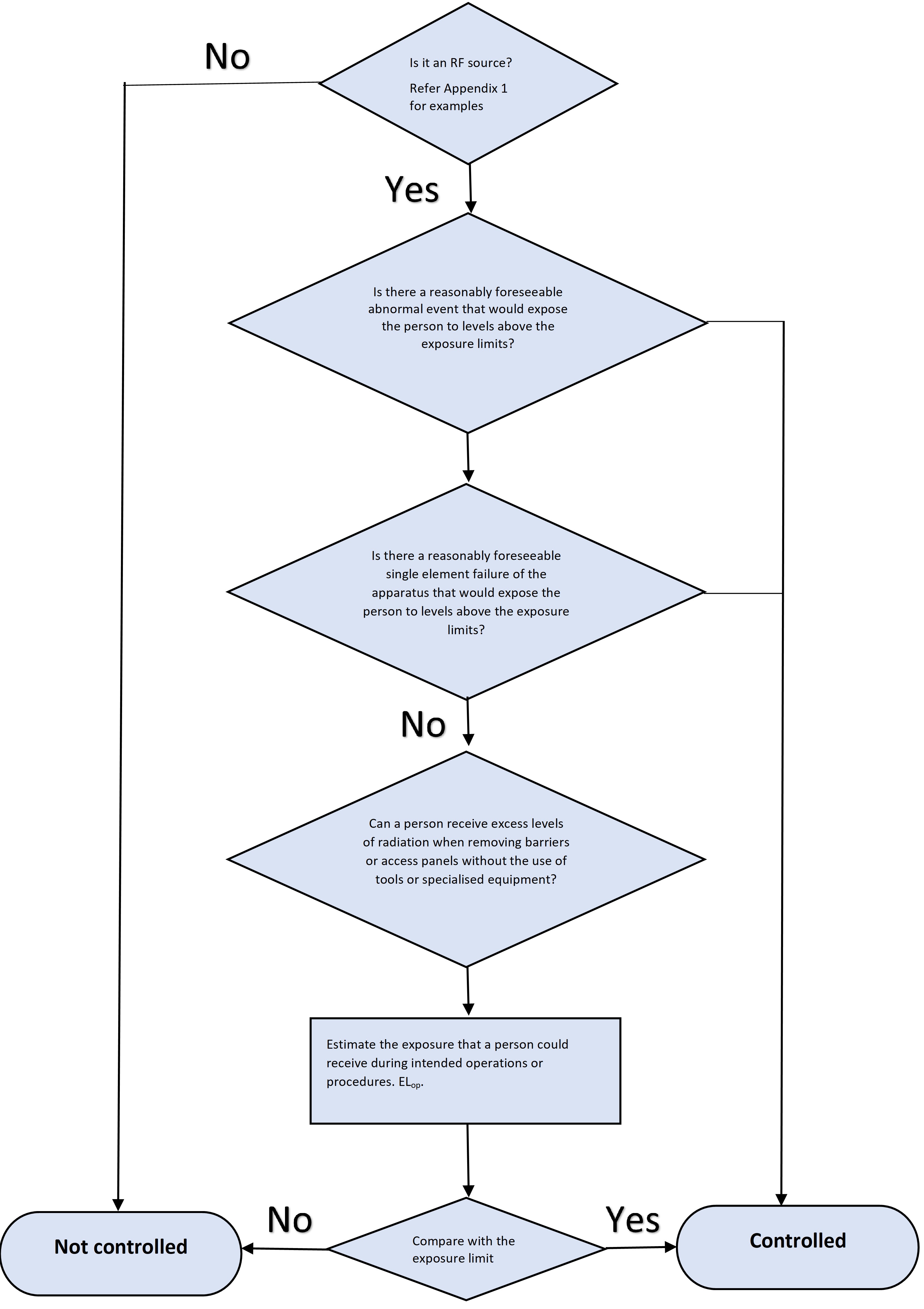
The following procedure describes how to go through these two criteria to determine whether an RF emitting device is classed as controlled or not.
4. Radiofrequency (high frequency) and low frequency radiation
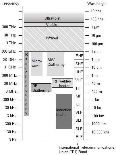
The part of the electromagnetic spectrum with high frequencies is in the range 3 kHz to 300 GHz and is referred to as radiofrequency (RF). The low frequency is in the range of 1 Hz to 100 kHz which include the 50/60 Hz electric and magnetic fields. The diagram below shows the divisions of the electromagnetic spectrum that are commonly accepted and will be used in this guide. Microwave (MW) frequency radiation is commonly used to denote a subset of RF radiation, typically at frequencies from 300 MHz to 300 GHz.
RF and MW radiation are forms of non-ionising radiation where individual photons are not energetic enough to break chemical bonds or remove electrons (ionisation). Ultraviolet, visible and infrared light are other forms of non-ionising radiation.
Figure 1: Electromagnetic spectrum with frequencies of some RF applications shown
Reference Documents
Radiation Protection Standard for Limiting Exposure to Radiofrequency Fields – 100 kHz to 300 GHz (2021), ARPANSA Radiation Protection Series S-1 (RPS S-1).
The ARPANSA RF Standard sets limits for human exposure to RF EMR in the frequency range 100 kHz to 300 GHz. The Standard also includes requirements for management of risk in occupational exposure and measures for protection of the general public together with additional information on measurement and assessment of compliance. Extracts from this document can be found in Appendix 2.
ICNIRP Guidelines for Limiting Exposure to Time-Varying Electric and Magnetic Fields 1Hz-100 kHz (2010), Health Physics 99(6):818-836.
The International Commission on Non-Ionizing Radiation Protection (ICNIRP) guidelines are aimed at preventing the established health effects resulting from exposure to ELF EMF. The ICNIRP ELF guidelines are consistent with ARPANSA’s understanding of the scientific basis for the protection of the general public and workers from exposure to ELF EMF. Extracts from this document can be found in Appendix 3.
Definitions
Exposure limits – Elimit: are defined in terms of basic restrictions for occupational and general public exposure as specified in RPS S-1 and the ICNIRP Guidelines. Different exposure limits apply for occupational exposure and exposure to the general public.
Controlled apparatus (non-ionising) as defined in the Act: an apparatus prescribed by the regulations that produces harmful non-ionising radiation when energised.
Procedure for determining controlled apparatus
This procedure (as illustrated by the flow chart below) will assist you to determine whether your apparatus is controlled or not.
This procedure (as shown in the flow chart below) will assist you to determine whether your apparatus is controlled or not.
1. A prescribed apparatus that produces non-ionizing radiation that could lead to a person being exposed to radiation levels exceeding the non-ionizing radiation exposure limits. For example, if the apparatus is one of the devices stated in Section 1 Controlled apparatus.
2. If there is a reasonably foreseeable abnormal event that could lead to a person being exposed to radiation levels in excess of the maximum exposure level, as specified in RPS S-1 or the ICNIRP Guidelines and reproduced in Appendix 2 and Appendix 3, the apparatus is classed as controlled apparatus. Examples of reasonably foreseeable abnormal events are possible exposure during normal maintenance, easy overriding of an interlock, entry into exclusion zones etc.
3. If there is a reasonably foreseeable single element failure of the apparatus that would lead to a person being exposed to levels above the maximum exposure level, then the apparatus is classed as controlled apparatus. An example of this is a malfunctioning interlock.
4. If the apparatus is enclosed the possibility of removal of the access panels or protective barriers has to be assessed. If there is no enclosure, choose no, and go to the next step. If a person can be exposed to levels above the maximum exposure level when removing protective barriers or access panels that do not require the use of tools or other specialized equipment, the apparatus is classed as controlled apparatus.
5. Estimate the exposure level that a person could receive in the course of intended operations and procedures, ELop. The distance to the unit during intended operations should be estimated and the expected exposure level calculated or measured. The attenuation provided by any fixed shields should be taken into account.
Compare with the exposure limits (Elimit) as specified in RPS S-1 or ICNIRP Guidelines.
If ELop > Elimit then the apparatus is classed as controlled apparatus
If ELop < Elimit then the apparatus is not classed as controlled apparatus
Appendix 1: Examples of RF emitting apparatus
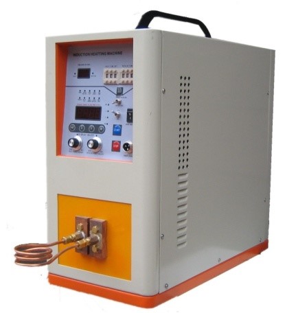
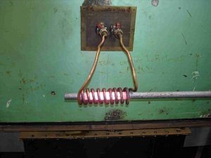
1. Induction heater
Definition: A heater that uses an induced electric current to produce heat.
Description: In an induction heater a conducting material is heated by induction of an electric current in the object to be heated. The resistance of the metal leads to heating. An induction heater consists of an electromagnet through which a high-frequency alternating current is passed. Heat can also be generated by magnetic hysteresis losses.
Induction heating provides a controllable and localized method of heating without contact between the heater and the components. Typical uses for induction heaters are heat treatment of metals, hardening of steel, annealing, bonding, curing and forging. A typical induction heater is shown below in Figure 2 and induction heating of a metal bar is shown in Figure 3.
Operating frequencies range from 50/60 Hz to over 1 MHz. Induction welders and induction solders are types of induction heaters and are included in the above category.
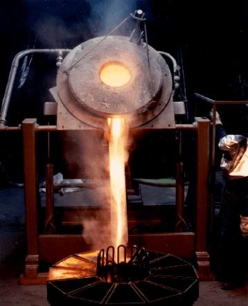
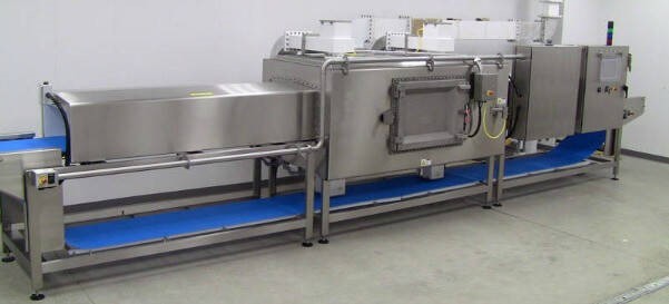
2. Induction furnace
Definition: A furnace that uses an induced electric current to heat a metal to its melting point.
Description: An induction furnace uses induction to heat a metal to its melting point. The heating mechanism is the same as in the induction heater. Common metals that are melted are iron, steel, copper, aluminium and precious metals. Melting and mixing rates can be controlled by selecting and varying the frequency and power. A picture of an induction furnace is shown in Figure 4.
Definition: A heating device in which heat is generated through a radiofrequency field. Industrial signifies that the apparatus is not used for domestic applications.
Description: The frequency of operation of RF heaters is in the range 10 MHz – 100 MHz, with output powers up to 100 kW. Common frequencies are 13.56 MHz, 27.12 MHz and 40.68 MHz. These frequencies have been designated to prevent interference with communications equipment.
RF heaters are used to heat, melt, dry or cure dielectric materials (insulators or poor conductors that can be polarized by an applied electric field). Plastic, glue and rubber are electrical and thermal insulators and consequently difficult to heat using conventional methods. These materials are well suited for heating with an RF heater. This is in contrast to induction heaters (defined in the previous section) which operate at lower frequencies and are used to heat materials which are good conductors of electricity. RF heaters can be used in industrial drying processes and are then often called RF dryers.
4. Industrial radiofrequency welder
Definition: A heating device in which heat is generated through a radiofrequency field and the heat is used to weld the material. Industrial signifies that the apparatus is not used for domestic applications.
Description: The heating mechanism is the same in an RF welder as in an RF heater. The material (often plastic) is heated to its melting point and the work pieces are joined together. RF welders are sometimes called RF sealers. An example of a RF welder is shown in Figure 5.
Definition: A tube containing plasma which is created by a radiofrequency field.
Description: An RF generator is attached to the RF tube and is used to generate the plasma. The tube typically contains a gas or a mixture of gases. As the gas is ionized, free electrons are accelerated in the field and collide with the atoms thereby exciting the atoms. As the atoms are de-excited photons are emitted resulting in visible or ultraviolet emission. A picture of an RF plasma tube is shown in Figure 6. Common frequencies are 13.56 MHz and 2.45 GHz.
6. Microwave or Radiofrequency (RF) diathermy equipment
Definition: Microwave diathermy equipment uses electromagnetic energy in the microwave frequency range (300 MHz to 300 GHz) for therapeutic purposes.
Whilst, RF diathermy equipment uses electromagnetic energy in the frequency range (3-30 MHz) for therapeutic purposes.
In Australia the only approved frequency for microwave diathermy treatment is 2450 MHz.
RF diathermy is sometimes referred to as shortwave diathermy. In Australia the only approved frequency for RF diathermy is 27.12 MHz. A picture of a diathermy unit is shown in Figure 7.
Note: Microwave and RF diathermy are not used very much nowadays and very few licence holders have this apparatus. In both microwave diathermy and RF diathermy heating of muscular tissue is performed for therapeutic reasons. In surgical diathermy a high-frequency electric current is made to pass through the body between two contact electrodes. The frequency is lower than for RF diathermy, typically 0.5–3 MHz. Surgical diathermy is not included in the above definition for microwave and radiofrequency diathermy equipment.
7. Industrial microwave processing system
Definition: A system where energy in the form of microwaves is used for heating or drying. Industrial signifies that the apparatus is not used for domestic applications.
Common microwave frequencies are 915 MHz, 2.45 GHz and 5.8 GHz. An industrial microwave is considered an industrial microwave processing system.
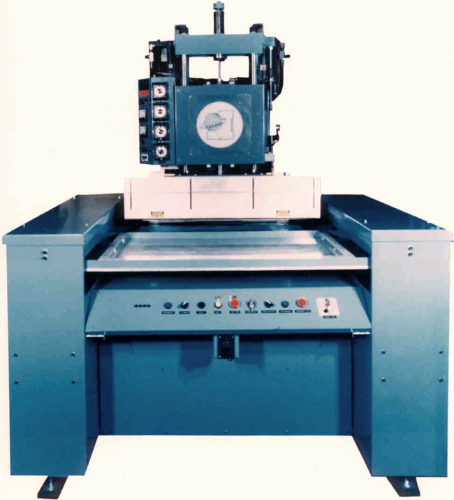
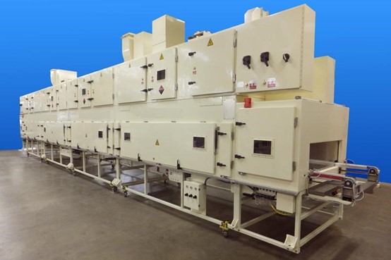
Definition: A system where energy in the form of radiofrequency waves is used for heating or drying. Industrial signifies that the apparatus is not used for domestic applications.
The most common RF frequencies are 13.56 MHz, 27.12 MHz and 40.68 MHz. Note that the definition for an industrial RF processing system is similar to the definition for an industrial RF heater. Typically an industrial RF processing system is a large enclosed unit used for large scale heating or drying (see Figure 9).
Radiofrequency and microwave processing systems are frequently used for heating and drying of materials such as paper, ceramics, food and plastics. Heating through RF and microwave is fast compared with conventional heating mechanisms which makes them a preferred option for pasteurization and sterilization. Microwave heating is a common choice in a laboratory environment. The heating mechanism is the same in RF heating, the only difference being the lower frequency. The selection of RF or microwave heating depends on the physical properties of the process. The penetration depth is greater for RF (longer wavelength) which can therefore be more suited for larger scale systems. RF systems also have a greater uniformity of heating.
Figure 9: Industrial RF processing system used for drying products
[Source: General Industry - Radio Frequency Co. - Industrial]
Appendix 2: Extracts from RPS S-1 Limiting Exposure to RF Fields – 100 kHz to 300 GHz (2021)
General information
The standard includes:
mandatory basic restrictions for both occupational and general public exposure involving the whole body and also for exposure over localised areas of the body
indicative reference levels for measurable quantities derived from the basic restrictions
approaches for verification of compliance with the standard
requirements for management of risk in occupational exposure and measures for protection of the general public
Basic Restrictions:
Mandatory limits on exposure to RF fields are based on established health effects and are termed ‘basic restrictions’. Depending on the frequency the physical quantities used to specify the basic restrictions are induced electric field (Eind), specific absorption rate (SAR), specific energy absorption (SA) and absorbed energy density (Uab). These quantities are often impractical to measure. Therefore reference levels are measured as an alternative means of showing compliance with the mandatory basic restrictions.
Reference Levels:
Reference levels using quantities that are more practical to measure have been developed. The reference levels have been conservatively formulated such that compliance with the reference levels will ensure compliance with the basic restrictions. Provided that all basic restrictions are met and adverse effects can be excluded, the reference levels may be exceeded. Hence the reference levels have been conservatively formulated such that compliance with the reference levels will ensure compliance with the basic restrictions. The relevant reference level quantities are incident electric field strength (Einc), incident magnetic field strength (Hinc), incident power density (Sinc), plane-wave equivalent incident power density (Seq), incident energy density (Uinc), and plane-wave equivalent incident energy density (Ueq), all measured outside the body, and electric current (I) inside the body.
Reference levels are given for occupational exposure and exposure to the general public. These groups are distinguished by their potential level of exposure.
In the extract from RPS S-1 below, reference levels are specified in Tables 4 - 7 and have been set to protect against effects associated with:
Table 4 whole body exposure (averaged over 30 minutes)
Table 5 local exposure (averaged over 6 minutes)
Table 6 brief local exposure (integrated over intervals between >0 and <6 minutes)
Table 7 instantaneous local exposure (peak instantaneous field strength)
Table 4: Reference levels for whole body exposure averaged over 30 minutes to RF electromagnetic fields from 100 kHz to 300 GHz (unperturbed rms fields)
Exposure Scenario
Frequency range
Incident E-field strength Einc
(V/m)
Incident H-field strength Hinc
(A/m)
Incident power density Sinc
(W/m2)
Occupational
0.1-6.943MHz
ES
4.9/fM
NA
>6.943-30 MHz
660/fM0.7
4.9/fM
NA
>30-400 MHz
61
0.16
10
400–2000MHz
3fM 0.5
0.008fM 0.5
fM /40
2–300 GHz
NA
NA
50
General Public
0.1-6.27MHz
ES
2.2/fM
NA
6.27-30 MHz
300/fM 0.7
2.2/fM
NA
>30-400 MHz
27.7
0.073
2
>400-2000 MHz
1.375fM 0.5
0.0037fM 0.5
fM/200
>2–300 GHz
NA
NA
10
Notes:
‘NA’ signifies ‘not applicable’ and does not need to be taken into account when determining compliance.
‘ES’ signifies that no reference level is available, as it would be greater than the reference level for spatial peak and temporal peak field strengths based on electrostimulation effects shown in Table 7.
fM is frequency in MHz.
Sinc, Einc and Hinc are to be averaged over 30 minutes, over the whole-body space. Temporal and spatial averaging of each of Einc and Hinc must be conducted by averaging over the relevant square values (see ICNIRP guidelines for limiting exposure to electromagnetic fields (100 kHz to 300 GHz), Health Physics, 118(5):483–524 for details) see International best practice - non-ionising radiation safety | ARPANSA.
For frequencies of 100 kHz to 30 MHz, regardless of the far-field/near-field zone distinctions, compliance is demonstrated if neither Einc nor Hinc exceeds the above reference level values.
For frequencies of >30 MHz to 2 GHz: a) within the far-field and radiating near field zones: compliance is demonstrated if either Sinc, Einc or Hinc, does not exceed the above reference level values (only one is required); Seq derived from either Einc or Hinc may be substituted for Sinc; b) within the reactive near-field zone: compliance is demonstrated if both Einc and Hinc do not exceed the above reference level values; Sinc cannot be used to demonstrate compliance, and so basic restrictions must be assessed.
For frequencies of >2 GHz to 300 GHz: a) within the far-field and radiating near field zones: compliance is demonstrated if Sinc does not exceed the above reference level values; Seq derived from either Einc or Hinc may be substituted for Sinc; b) within the reactive near-field zone, reference levels cannot be used to determine compliance, and so basic restrictions must be assessed.
Table 5: Reference levels for local exposure averaged over 6 minutes, to electromagnetic fields from 100 kHz to 300 GHz (unperturbed rms fields)
Exposure Scenario
Frequency range
Incident E-field strength Einc
(V/m)
Incident H-field strength Hinc
(A/m)
Incident power density Sinc
(W/m2)
Occupational
0.1-0.135 MHz
ES
ES
NA
>0.135-10 MHz
ES
10.8/fM
NA
>10-30 MHz
1504/fM0.7
10.8/fM
NA
>30-400 MHz
139
0.36
50
>400-2000 MHz
10.58fM0.43
0.0274fM0.43
0.29fM0.86
>2-6 GHz
NA
NA
200
>6-<300 GHz
NA
NA
275/fG0.177
300 GHz
NA
NA
100
General Public
0.1-0.233 MHz
ES
ES
NA
>0.233-10 MHz
ES
4.9/fM
NA
>10-30 MHz
671/fM 0.7
4.9/fM
NA
>30-400 MHz
62
0.163
10
>400-2000 MHz
4.72fM 0.43
0.0123fM 0.43
0.058fM 0.86
>2-6 GHz
NA
NA
40
>6-<300 GHz
NA
NA
55/fG 0.177
300 GHz
NA
NA
20
Notes:
‘NA’ signifies ‘not applicable’ and does not need to be taken into account when determining compliance.
‘ES’ signifies that no reference level is available, as it would be greater than the reference level for spatial peak and temporal peak field strengths based on electrostimulation effects shown in Table 7.
fM is frequency in MHz; fG is frequency in GHz.
Sinc, Einc and Hinc are to be averaged over 6 minutes, and where spatial averaging is specified in Notes 6-7, over the relevant projected body space. Temporal and spatial averaging of each of Einc and Hinc must be conducted by averaging over the relevant square values (see ICNIRP guidelines for limiting exposure to electromagnetic fields (100 kHz to 300 GHz), Health Physics, 118(5):483–524 for details) see link International best practice - non-ionising radiation safety | ARPANSA to the ICNIRP website.
For frequencies of 100 kHz to 30 MHz, regardless of the far-field/near-field zone distinctions, compliance is demonstrated if neither peak spatial Einc nor peak spatial Hinc, over the projected whole-body space, exceeds the above reference level values.
For frequencies of >30 MHz to 6 GHz: a) within the far-field and radiating near field zones, compliance is demonstrated if one of peak spatial Sinc, Einc or Hinc, over the projected whole-body space, does not exceed the above reference level values (only one is required); Seq derived from either Einc or Hinc may be substituted for Sinc; b) within the reactive near-field zone: compliance is demonstrated if both Einc and Hinc do not exceed the above reference level values; Sinc cannot be used to demonstrate compliance; for frequencies >2 GHz, reference levels cannot be used to determine compliance, and so basic restrictions must be assessed.
For frequencies of >6 GHz to 300 GHz: a) within the far-field and radiating near field zones, compliance is demonstrated if Sinc, averaged over a square 4 cm2 projected body surface space, does not exceed the above reference level values; Seq derived from either Einc or Hinc may be substituted for Sinc; b) within the reactive near-field zone, reference levels cannot be used to determine compliance, and so basic restrictions must be assessed.
For frequencies of >30 GHz to 300 GHz, exposure averaged over a square 1-cm2 projected body surface space must not exceed twice that of the square 4 cm2 Sinc restrictions.
Table 6: Reference levels for local exposure, integrated over intervals of between >0 and <6 minutes to RF electromagnetic fields from 100 kHz to 300 GHz (unperturbed rms fields)
Exposure Scenario
Frequency range
Incident energy density Uinc
(kJ/m2)
Occupational
100 kHz – 400 MHz
NA
>400 – 2000 MHz
0.29fM0.86 x 0.36(0.05+0.95[t/360]0.5)
>2 – 6 GHz
200 x 0.36(0.05+0.95[t/360]0.5)
>6 – <300 GHz
275/fG0.177 x 0.36(0.05+0.95[t/360]0.5)
300 GHz
100 x 0.36(0.05+0.95[t/360]0.5)
General Public
100 kHz – 400 MHz
NA
>400 – 2000 MHz
0.058fM0.86 x 0.36(0.05+0.95[t/360]0.5)
>2 – 6 GHz
40 x 0.36(0.05+0.95[t/360]0.5)
>6 – <300 GHz
55/fG0.177 x 0.36(0.05+0.95[t/360]0.5)
300 GHz
20 x 0.36(0.05+0.95[t/360]0.5)
Notes:
‘NA’ signifies ‘not applicable’ and does not need to be taken into account when determining compliance.
fM is frequency in MHz; fG is frequency in GHz; t is the exposure time interval in seconds, such that exposure from any pulse, group of pulses, or subgroup of pulses in a train, as well as from the summation of exposures (including non-pulsed RF electromagnetic fields), delivered in t seconds, must not exceed these reference level values for any time 0 < t < 360 s.
Uinc is to be calculated over time t, and where spatial averaging is specified in Notes 5-7, over the relevant projected body space.
For frequencies of 100 kHz to 400 MHz, >0 to <6-minute restrictions are not required and so reference levels have not been set.
For frequencies of >400 MHz to 6 GHz: a) within the far-field and radiating near field zones: compliance is demonstrated if peak spatial Uinc, over the projected whole-body space, does not exceed the above reference level values; Ueq derived from either Einc or Hinc may be substituted for Uinc; b) within the reactive near-field zone, reference levels cannot be used to determine compliance, and so basic restrictions must be assessed.
For frequencies of >6 GHz to 300 GHz: a) within the far-field or radiative near-field zone, compliance is demonstrated if Uinc, averaged over a square 4 cm2 projected body surface space, does not exceed the above reference level values; Ueq derived from either Einc or Hinc may be substituted for Uinc; b) within the reactive near-field zone, reference levels cannot be used to determine compliance, and so basic restrictions must be assessed.
For frequencies of >30 GHz to 300 GHz: exposure averaged over a square 1cm2 projected body surface space must not exceed 275/fG0.177 x 0.72(0.025+0.975[t/360]0.5) kJ/m2 for occupational and 55/fG0.177 x 0.72(0.025+0.975[t/360]0.5) kJ/m2 for general public exposure.
Table 7: Reference levels for spatial peak and temporal peak field strength to RF electromagnetic fields from 100 kHz to 300 GHz (unperturbed rms fields)
Exposure Scenario
Frequency range
Incident E-field strength Einc
(V/m)
Incident H-field strength Hinc
(A/m)
Occupational
100 kHz – 10 MHz
170
80
General Public
100 kHz – 10 MHz
83
21
Notes:
Regardless of the far-field/near-field zone distinction, compliance is demonstrated if neither the temporal nor spatial peak Einc or Hinc, over the space occupied by the body, exceeds the above reference level values.
The figures for occupational and general public reference levels for whole body and local exposure to RF electromagnetic fields as specified in tables 4 and 5 can be found in RPS S-1 Schedule 1.
Reference levels for limb currents
Limb current reference levels have been set to account for effects of grounding near human body resonance frequencies that might otherwise lead to reference levels underestimating exposures within tissue at certain RF electromagnetic field frequencies (averaged over 6 minutes – see Table 8) Limb current reference levels are only relevant in exposure scenarios where a person is not electrically isolated from a ground plane.
Table 8: Reference levels for current induced in any limb averaged over 6 minutes at frequencies between 100 kHz and 110 MHz
Exposure Scenario
Frequency range
Current I (mA)
Occupational
10 MHz – 110 MHz
100
General Public
10 MHz – 110 MHz
45
Notes:
Current intensity values must be determined by averaging over the relevant square values (see ICNIRP guidelines for limiting exposure to electromagnetic fields (100 kHz to 300 GHz), Health Physics, 118(5):483–524 for details), the document can be downloaded from the ARPANSA website link International best practice - non-ionising radiation safety | ARPANSA to the ICNIRP website.
Limb current intensity must be evaluated separately for each limb.
Limb current reference levels are not provided for any other frequency range.
Limb current reference levels are only required for cases where the human body is not electrically isolated from a ground plane.
Tables 4 to 8 specify averaging and integrating times of the relevant exposure quantities to determine whether personal exposure level is compliant with the Standard. These averaging and integrating times are continuous periods.
Guidance for contact currents
Exposure due to contact currents is indirect, in that it requires an intermediate conducting object to transduce the field. This makes contact current exposure unpredictable, due to both behavioural factors (e.g., grasping versus touch contact) and environmental conditions (e.g., configuration of conductive objects), and reduces this Standard’s ability to protect against them. Accordingly, the ICNIRP guidelines and the Standard do not provide restrictions for contact currents, and instead provide ‘guidance’ to assist those responsible for transmitting high-power RF fields to understand contact currents, the potential hazards, and how to mitigate such hazards.
In determining the likelihood and nature of the hazard due to potential contact current scenarios, ICNIRP views the following as important for the Responsible Person in managing risk associated with contact currents within the 100 kHz to 110 MHz region.
(a) Contact current thresholds for reversible, mild pain, for adults and children, are likely to be approximately 20 mA and 10 mA respectively.
(b) Contact current magnitude will increase as a function of field strength and is affected by conducting-object configuration such as the proximity to the original source and the angular alignment to the original source.
(c) Risk of contact current hazards can be minimized by training workers to avoid contact with conducting objects, but where contact is required, the following factors are important:
i. Large conducting objects should be connected to ground (grounding).
ii. Workers should make contact via insulating materials or PPE (e.g., RF protective gloves).
iii. Reducing or removing the RF power at the original source can eliminate the risk.
iv. Workers should be made aware of the risks, including the possibility of ‘surprise’, which may impact on safety in ways other than the direct impact of the current on tissue (for example, by causing accidents when working at heights).
Appendix 3: Extracts from the ICNIRP Guidelines for Limiting Exposure to Time-Varying Electric and Magnetic Fields 1Hz-100 kHz (2010)
General information
This publication establishes guidelines for limiting exposure to electric and magnetic fields in the low frequency range of the electromagnetic spectrum. Separate guidance is given for occupational and general public exposures.
Reference Levels
A summary of the reference levels recommended for occupational and general public exposures to electric and a magnetic field is given in Tables 3 and 4.
Table 3: Reference levels for occupational exposure to time-varying electric and magnetic fields (unperturbed rms fields)
Frequency range
E-field strength
E (kV/m-1)
Magnetic-field strength
H (A m-1)
Magnetic flux density
B (T)
1 Hz-8 Hz
20
1.63x10⁵/f2
0.2/f2
8 Hz-25 Hz
20
2x10⁴/f
2.5x10⁻²/f
25 Hz-300 Hz
5x10²/f
8x10²
1x10⁻³
300 Hz-3 kHz
5x10²/f
2.4x10⁵/f
0.3/f
3 kHz-10 MHz
1.7x10⁻¹
80
1x10⁻⁴
Notes:
f in Hz
Refer ICNIRP Guidelines separate sections for advice on non-sinusoidal and multiple frequency exposure
To prevent indirect effects especially in high electric fields, see section on “Protective measures” in the ICNIRP Guidelines
In the frequency range above 100 kHz, RF specific reference levels need to be considered additionally.
Table 4: Reference levels for general public exposure to time-varying electric and magnetic fields (unperturbed rms values)
Frequency range
E-field strength
E (kV/m-1)
Magnetic-field strength
H (A m-1)
Magnetic flux density
B (T)
1 Hz-8 Hz
5
3.2x10⁴/f2
4x10⁻²/f2
8 Hz-25 Hz
5
4x10³/f
5x10⁻³/f
25 Hz-50 Hz
5
1.6x10²
2x10⁻⁴
50 Hz-400 Hz
2.5x10²/f
1.6x10²
2x10⁻⁴
400 Hz-3 kHz
2.5x10²/f
6.4x10⁴/f
8x10⁻²/f
3 kHz-10 MHz
8.3x10⁻²
21
2.7x10⁻⁵
Notes:
f in Hz
Refer ICNIRP Guidelines separate sections for advice on non-sinusoidal and multiple frequency exposure
In the frequency range above 100 kHz, RF specific reference levels need to be considered additionally
This document is provided to assist applicants and licence holders assess UV emitting apparatus. It may also be useful for non-licence holders to gain an understanding of the hazard of some typical UV emitting apparatus. It contains case studies of apparatus that have been assessed by ARPANSA.
If you have any questions on how to evaluate your specific apparatus please contact your regulatory officer or send an email to: licenceadmin@arpansa.gov.au.
Note: Subsection 44(7) of the Regulations exempts dealings with the following UV emitting apparatus:
an artificial optical source emitting ultraviolet A radiation (315 – 400 nm)
a completely enclosed apparatus containing an ultraviolet radiation light source (e.g., a spectrophotometer)
a biological safety cabinet (laminar flow or biohazard) with a failsafe interlocking system
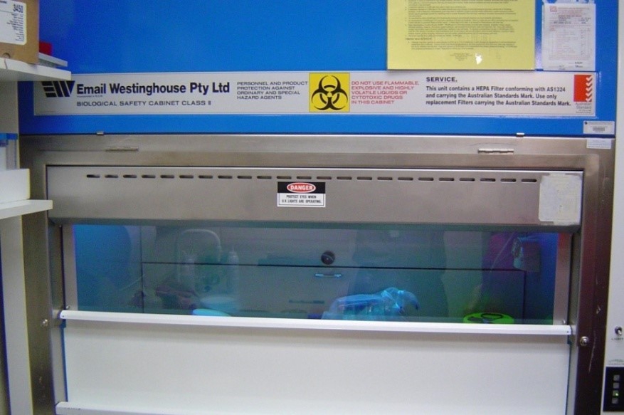
The biological safety cabinet emits at a wavelength of 254 nm, which is in the UVC region (180 – 280 nm). It is a germicidal lamp which means that the emission levels will be well above the exposure limits.
The lower access panel can be taken off while the UV lamp is energized.
There is no interlock or the interlock can be overridden.
Assessment
During intended operations or procedures the exposure limits will not be exceeded, as the window and access panel will protect the user. The UV light is only used between procedures for disinfecting. It should not be used while samples are being handled.
It is reasonably foreseeable that a person could remove the access panel while the UV light is on and receive an exposure.
This biological safety cabinet is classed as controlled apparatus
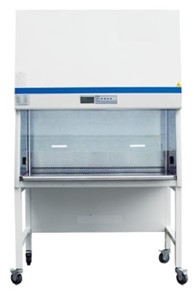
2. Biological safety cabinet – Example 2
Details of the apparatus
The biological safety cabinet emits UV light at 254 nm (UVC). It is a germicidal lamp which means that the emission levels will be well above the exposure limits.
The fluorescent lamps and UV light cannot work simultaneously as they are electronically interlocked.
While the unit is in UV mode the sliding window cannot be opened.
UV light cannot be turned on while the sliding door is open.
If a fault occurred and the window could be opened electronically or manually, an interlock will cut the UV emission. The interlock is failsafe (meaning that if it should fail the UV emission will terminate) and hard to override.
Assessment
During intended operations or procedures the exposure limits will not be exceeded.
Due to the robust failsafe, interlock there is no reasonably foreseeable abnormal event that would expose a person to levels above the exposure limits.
As the interlock is failsafe there is no reasonably foreseeable single element failure that would expose a person to levels above the exposure limits.
This biological safety cabinet is not classed as controlled apparatus
Comment
This assessment is based on the above criteria for a biological safety cabinet. Most standard older biological safety (laminar flow/biohazard) cabinets containing a UV source are classed as controlled apparatus. Please contact an ARPANSA regulatory officer to discuss if you have a biological safety cabinet that you believe is not classed as controlled apparatus on the same grounds as in the example above.
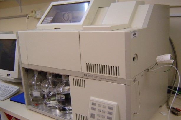
3. High-performance liquid chromatography (HPLC)
Details of the apparatus
The UV light source is completely enclosed
Low UV emission
Assessment
During intended operations or procedures the exposure limits will not be exceeded.
It is not reasonably foreseeable that a person could access the UV source and receive exposures above the exposure limit.
A person cannot remove access panels without use of tools or specialised equipment.
The apparatus is not classed as controlled apparatus
Comment
If a unit is a standard HPLC with properties similar to the one above it is automatically classed as not controlled. There is no need to assess it against the regulatory guide.
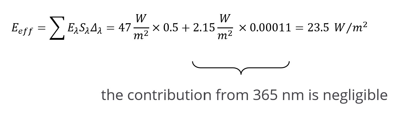
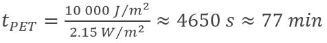
Calculate the effective irradiance according to RPS 12:
At 20 mm:
At 20 cm:
It is reasonably foreseeable that someone would be exposed for more than 2 minutes at 20 cm distance or more than 1.3 seconds at 20 mm distance. This means that the UVR exposure limit could be exceeded.
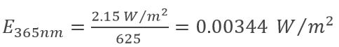
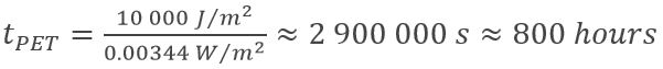
Eye UVA (315 – 400 nm) exposure:
At 20 mm: E365nm= 2.15 W/m2
At 50 cm:
The exposure limit at 50 cm
Maximum UVA exposure for the eyes will not be exceeded. The exposure to the skin will be the limiting factor.
It is reasonably foreseeable that a person could be exposed to levels above the exposure limit.
The apparatus is classed as controlled apparatus
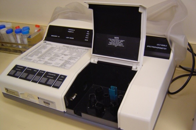
5. Spectrophotometer
Details of the apparatus
The UV light source is enclosed during operation
Low UV emission
Assessment
During intended operations or procedures the exposure limits will not be exceeded.
It is not reasonably foreseeable that a person could access the UV source and receive exposures above the exposure limit.
The apparatus is not classed as controlled apparatus
Comment
If a unit is a standard spectrophotometer with properties similar to the one above it is automatically classed as not controlled. There is no need to assess it against the regulatory guide.
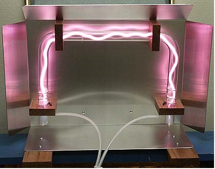
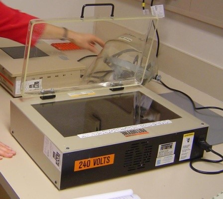
6. Transilluminator
Details of the apparatus
The emission of transilluminators is typically 254 nm, 312 nm or 366 nm.
Transilluminators are powerful sources of UV radiation. Emission levels are above exposure limits. Transilluminators, used in research can be a significant source of occupational exposure to UVR. Hands, arms, face and eyes are likely sites of injury. Working unprotected for even a few minutes can cause injury.
Assessment
Reasonably foreseeable abnormal events where exposure limits could be exceeded are:
shielding is removed or non-existent
PPE is not worn or is not appropriate
Both transilluminators are classed as controlled apparatus
Comment
There have been a number of incidents where the user of a transilluminator developed erythema because appropriate PPE was not used and a shield was not present.
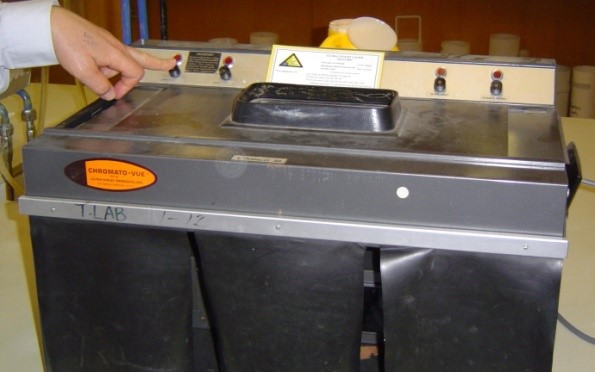
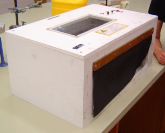
7. UV light box
Details of the apparatus
Homemade units
Manual switches turns UV source on and off
Intensity levels unknown
There is no interlock or fixed shielding
Assessment
It is reasonably foreseeable that someone might place their hand in the box while the UV source in on. If the levels are high enough the exposure levels could be exceeded.
The apparatus is classed as controlled apparatus
Comment
If emission levels are measured and found to be low (no reasonably foreseeable abnormal event where a person would be exposed to levels above the exposure limit) the apparatus is not controlled.
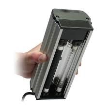
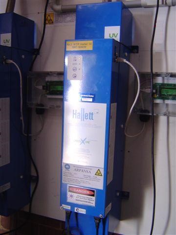
8. Water steriliser – Example 1
Details of the apparatus
Water steriliser where UV lamp is used to kill bacteria as the water flows past.
Germicidal action which means that emission levels are high (primarily UVC – 254 nm).
UV light is leaking out from the back of the unit. The unit is completely enclosed apart from this opening. The emission levels of the escaping UV light have not been quantified.
The enclosure is interlocked.
Assessment
We can assume that the intensity of the escaping light is low so that during intended operations or procedures the exposure limits will not be exceeded (a person will not normally be close to the unit).
It is reasonably foreseeable that a person could hold their hand close to the unit and be exposed to the escaping light. As we do not know the intensity of the escaping light we make the conservative assumption that the exposure limit can be exceeded.
The apparatus is classed as controlled apparatus
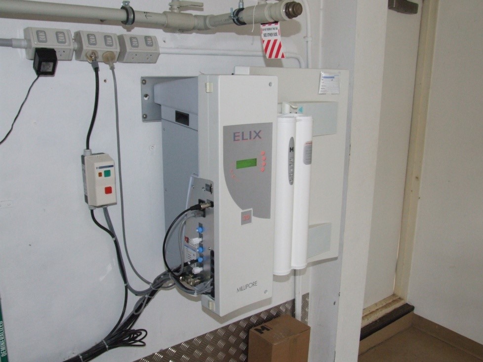
9. Water steriliser – Example 2
Details of the apparatus
Water steriliser where UV lamp is used to kill bacteria as the water flows past.
The emission of the UV light is at 254 nm (UVC). Germicidal action which means that emission levels are high.
The unit is fully enclosed and the housing is not interlocked.
A screwdriver is needed to open the housing.
Assessment
During intended operations or procedures the exposure limits will not be exceeded as the source is completely enclosed.
A reasonably foreseeable abnormal event that would expose a person to levels above the exposure limit could be exposure during maintenance when the UV lamp is replaced. The standard operating procedure for changing the lamp illustrates that the lamp is completely enclosed in a special housing, and that the power has to be switched off before you can access the UV lamp. From this it is concluded that there is no risk of exposure during the process of changing the lamp.
Excess levels of radiation are not accessible under a reasonable foreseeable single element failure of the apparatus and the source cannot be accessed without the use of tools or specialised equipment.
The apparatus is not classed as controlled apparatus